Hdkeyb: Difference between revisions
| (2 intermediate revisions by the same user not shown) | |||
| Line 1: | Line 1: | ||
=USB keyboard and display= | =USB keyboard and display= | ||
This circuit is intented to connect HD44780 compatible LCD display and matrix keyboard 4x4 to PC using only one USB cable. | |||
It uses FT232R in bitbang mode ([[Usbio]]). | |||
Keyboard rows are adressed by setting address lines A2:A0 through multiplexer '138. Keyboard columns are read by C4:C1. All diodes are mandatory otherwise pressing key can damage the '138 or can cause bad display function. | |||
Display is acessed when A3 is pulled low. In this case the keyboard rows are not active and [[Usbio]] communicates directly with display. | |||
Good idea is to use synchronous bitbang mode for communication. Because switching between write and read is slow, we can send five bytes to select rows and to read five bytes with column data. This takes about 30ms. Switching direction after every row change would be 5x slower. | |||
This is the reason I don't use READY flag althrough it is present. It is very slow so better is to choose proper bitrate, prepare data in buffer and send it in one chunk. | |||
=Circuit diagram= | =Circuit diagram= | ||
[[Image:Hdkeyb1s120.png|none|frame|Circuit diagram of Hdkeyb]] | [[Image:Hdkeyb1s120.png|none|frame|Circuit diagram of Hdkeyb]] | ||
Usbio is described [[Usbio|here]]. | |||
=PCB= | =PCB= | ||
<gallery> | <gallery> | ||
| Line 11: | Line 23: | ||
</gallery> | </gallery> | ||
Note: 600 DPI have images in Full resolution, MediaWiki uses thumbnails. | Note: 600 DPI have images in Full resolution, MediaWiki uses thumbnails. | ||
Note: 7805 is [[78xx soldering|soldered on top side]] but with cooling plate | Note: 7805 is [[78xx soldering|soldered on top side]] but with cooling plate up. Verify connection before plug power supply! | ||
Latest revision as of 14:11, 2 November 2009
USB keyboard and display
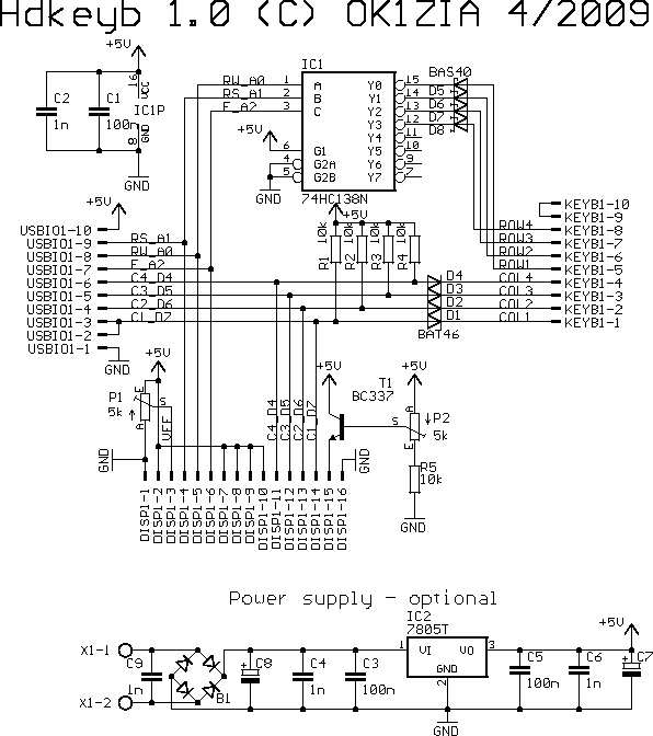
This circuit is intented to connect HD44780 compatible LCD display and matrix keyboard 4x4 to PC using only one USB cable. It uses FT232R in bitbang mode (Usbio).
Keyboard rows are adressed by setting address lines A2:A0 through multiplexer '138. Keyboard columns are read by C4:C1. All diodes are mandatory otherwise pressing key can damage the '138 or can cause bad display function.
Display is acessed when A3 is pulled low. In this case the keyboard rows are not active and Usbio communicates directly with display.
Good idea is to use synchronous bitbang mode for communication. Because switching between write and read is slow, we can send five bytes to select rows and to read five bytes with column data. This takes about 30ms. Switching direction after every row change would be 5x slower.
This is the reason I don't use READY flag althrough it is present. It is very slow so better is to choose proper bitrate, prepare data in buffer and send it in one chunk.
Circuit diagram

Usbio is described here.
PCB
-
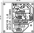
PCB bottom side (600 DPI)
-
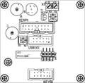
Components placement top
-
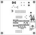
Components placement bottom
Note: 600 DPI have images in Full resolution, MediaWiki uses thumbnails. Note: 7805 is soldered on top side but with cooling plate up. Verify connection before plug power supply!


