Usb2ttl: Difference between revisions
Jump to navigation
Jump to search
Created page with '=USB converter for Rotar 4.x= <!--none|frame|Principe of rotator 4.7 =Gallery= <gallery> Image:Rotar47usw_1.jpg|Control box made by OK1USW Image:Rotar47usw...' |
|||
| (One intermediate revision by the same user not shown) | |||
| Line 1: | Line 1: | ||
=USB converter for Rotar 4.x= | =USB converter for Rotar 4.x= | ||
<!--[[Image:Rotar47.png|none|frame|Principe of rotator 4.7]] | <!--[[Image:Rotar47.png|none|frame|Principe of rotator 4.7]] | ||
| Line 14: | Line 17: | ||
=PCB= | =PCB= | ||
<gallery> | <gallery mode="packed" widths="640px"> | ||
Image:Usb2ttlb600.png|PCB bottom side (600 DPI) | Image:Usb2ttlb600.png|PCB bottom side (600 DPI) | ||
Image:Usb2ttloa.png|Components placement top | Image:Usb2ttloa.png|Components placement top | ||
| Line 20: | Line 23: | ||
</gallery> | </gallery> | ||
Note: 600 DPI have images in Full resolution, MediaWiki uses thumbnails. | Note: 600 DPI have images in Full resolution, MediaWiki uses thumbnails. | ||
=ChangeLog= | |||
* 2012-04-24 - fixed old schematics | |||
* 2012-04-24 - changed R19 to 680R | |||
Latest revision as of 19:53, 30 August 2015
USB converter for Rotar 4.x
Circuit diagram

PCB
-
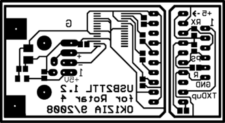 PCB bottom side (600 DPI)
 -
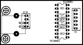 Components placement top
 -
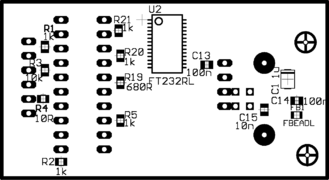 Components placement bottom


Note: 600 DPI have images in Full resolution, MediaWiki uses thumbnails.
ChangeLog
- 2012-04-24 - fixed old schematics
- 2012-04-24 - changed R19 to 680R